Demystifying Hydraulic Servo Valve Performance: A Guide to Key Parameters
The hydraulic servo valve mainly refers to the Electro-hydraulic Servo Valve, which outputs modulated flow and pressure after receiving electrical anaLog signals.
It is both an electro-hydraulic conversion element and a power amplification element, which can convert low-power weak electrical input signals into high-power
hydraulic energy (flow and pressure,output. In the electro-hydraulic servo system, it connects the electrical part with the hydraulic part to achieve the conversion
of electro-hydraulic signals and hydraulic amplification. The electro-hydraulic servo valve is the core of the electro-hydraulic servo system control.

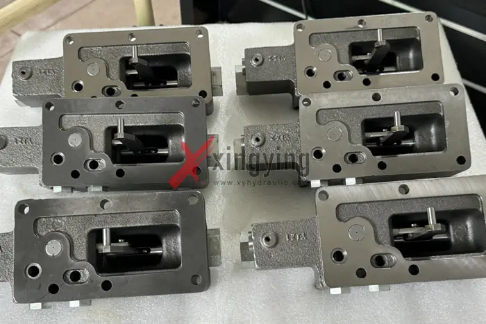
Eaton 4621 4623 5421 5423 6423 7620 Hydraulic Control
1,Rated current
The input control current (excluding zero bias current,specified for any polarity of the coil to produce a rated flow, expressed in milliamps (mA). Usually, the rated current refers to single coil connection, differential connection, or parallel connection. When working in series, the rated current is half of the rated current for the above working modes.
2,Zero current
For a differentially connected coil, the current flowing through each coil when the differential current is zero.
3,Overload current
The maximum allowable current flowing through the torque motor coil. The recommended overload current is twice the maximum current flowing through the torque motor coil.
4,Coil resistance
The DC resistance of each coil is expressed in ohms (Ω). The coil resistance tolerance is ±10% of the nominal resistance value. In the same servo valve, the difference between the resistance values of the two coils is not greater than 5% of the nominal resistance value.
5,Coil inductance
The inductance component of the coil impedance is denoted in H. The coil's inductance is related to the oil supply pressure, input current amplitude, and frequency. It is specified that the control current frequency is 60Hz, with a peak-to-peak value of ¼ of the rated current, and is measured under the rated oil supply pressure.
Coil inductance is usually measured in the state of coil series connection.
6,Rated flow
The specified control flow output corresponding to the rated current and given oil supply pressure and load pressure conditions. Usually, the rated flow is specified as the no-load flow corresponding to the rated current when the pressure drop is equal to the rated oil supply pressure, expressed in liters per minute.
7,Flow gain
The slope of the flow curve, expressed in liters per minute per milliampere.
8,Internal leakage
When the control flow is zero, the flow rate from the return oil window is expressed in liters per minute. It varies with the control current and takes the maximum value as the internal leakage.
9,Hysteresis loop
Between the positive and negative rated currents, a cycle is performed at a speed less than the dynamic characteristic (usually not greater than 0.1Hz), resulting in a maximum difference between the control currents for the same flow rate to and from. The ratio of this difference to the rated current is expressed as a percentage.
10,Linearity
The non-linearity of the flow curve. The ratio of the maximum deviation of the nominal flow gain line to the rated current, expressed as a percentage, using the nominal flow curve.
11,Symmetry
The inconsistency of the flow gain between two polarities. Take the ratio of the difference between the nominal flow gain of one polarity and the nominal flow gain of the other polarity to the larger of the two, expressed as a percentage.
12,Overlap
When the slide valve is at the zero position, the axial position relationship between the fixed throttle edge and the movable throttle edge is determined. For servo valves, the measurement method for overlap is as follows: for each polarity, a nominal flow curve approximation is made to the straight line portion, and the total interval between the zero flow points of the two extension lines is expressed as a percentage of the rated current.

Zero overlap is the condition where there is no gap between the two extensions of the nominal flow curve. Positive overlap is the overlap that causes the slope of the nominal flow curve in the zero region to decrease. Negative overlap is the overlap that causes the slope of the nominal flow curve in the zero region to increase. The tolerance for zero overlap is specified as 2.5% positive overlap to 2.5% negative overlap.
13,Pressure gain
When the control flow is zero, the rate of change of the load pressure drop to the control current is expressed in megapascal per milliampere (MPa/mA). Usually, the pressure gain is specified as the average slope of the load pressure drop to the control current curve within ±40% of the maximum load pressure drop. Similarly, the pressure gain can also be specified as the percentage change in load pressure drop relative to the rated supply pressure when the valve is at zero position and inputting 1% rated current.
14,Zero deviation
The state where the no-load flow is zero is called the zero position. The ratio of the control current required to bring the valve to the zero position (excluding the hysteresis effect of the valve,to the rated current, expressed as a percentage, is called the zero bias.
15,Resolution
The minimum increment of control current that causes a change in the control flow of the valve. It varies depending on the magnitude of the control current and the length of residence time. The ratio of the maximum value to the rated current is expressed as a percentage.
16,Frequency characteristics
When the control current varies sinusoidally within a certain frequency range, the complex ratio of the no-load control flow to the control current is measured. The input amplitude, operating temperature, oil supply pressure, and other operating conditions all have an impact on the frequency characteristics of the valve. Usually, under standard test conditions, the calibration is performed with a peak-to-peak value of the control current of 50% of the rated current. The frequency is measured using the frequency corresponding to an amplitude of -3 decibels (dB,and a phase angle of -90°. The amplitude ratio of the valve frequency characteristics should not exceed +2 decibels (dB).
Why Choose XingYing Hydraulic as Your Supplier?
1.Direct from Manufacturer: Benefit from competitive pricing on top-quality hydraulic products, sourced directly from our factory in China.
2.Custom Solutions: Our expertise allows us to tailor hydraulic components to your precise requirements, ensuring optimal performance.
3.Reliable Supply: Count on us as your trusted supplier for consistent quality and timely delivery, backed by our reputation in the industry.